Modifed DB8 COnstruction Details
All of the reflector rods used are 38" long, with the exception of the two inner most rods on each side, which are 37". There is no reason for that other than I started out cutting at 37" and then whimsically changed my mind midstream. I'm simply confessing that I had no logical reason for it, primarily because it is noticable in the pictures and thus there might be questions about it. [For those speculating about Hi-VHF response, a normal reflector for the VHF Channel 7 would be about 35", and I suspect that any rod length between 35" and 38" inches will perfrom similarly].
Also, the uppermost rod, the most likely bird perch, is from 3/8" round tubing, and the bottom most rod 3/8" tubing as well just to electrically match. All others are 3/16" tubing.
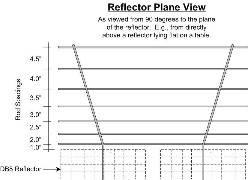
This illustration provides details of the rod spacings. I experimented with a number of different physical spacings and arrived at this staggered spacing only empirically. I found that more reflectors spaced closer together favored the high end, and fewer spaced further apart favored the low end (but also got way too big to be feasible). I stumbled on this staggered arrangement only after observing that the horizontal members of the 91XG screen have similarly staggered spacings.
The exact values were arrived at by experimenting with a number of spacings, balancing improvement against size and stability.
The two vertical supporting rods are also 3/8" stock.
Construction began with two approximately 28" long 3/8" aluminum rods for support members. I bent them on my knee arriving at about a 3" radius bend. The radius of this bend is necessary to get the inner most rod mounted correctly on the same plane as the existing DB8 reflector.
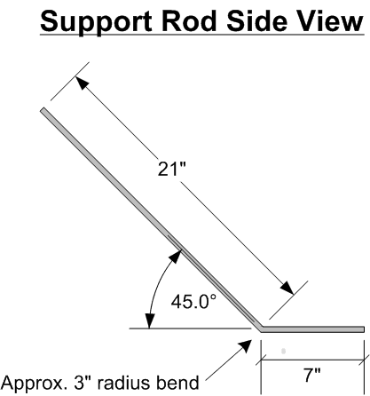
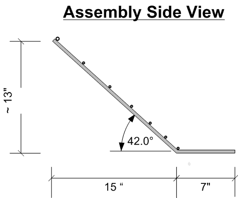
When these rods are attached to the supporting vertical members they are rotated outwards at an angle of about 25 degrees.
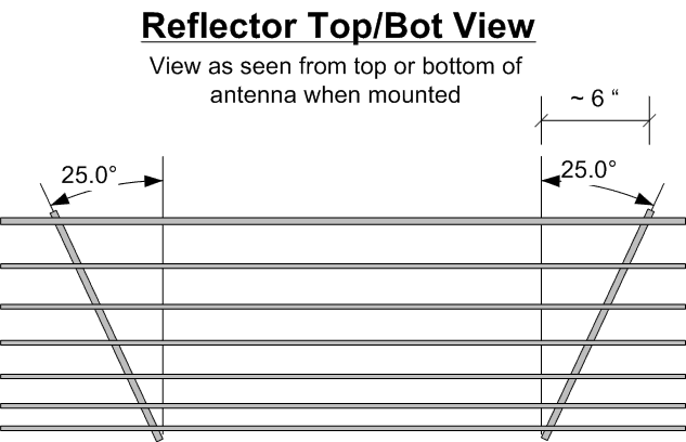
This results in an effective reflector angle of 42 degrees, and that was intentional because it was at this angle that the assembled reflector demonstrated optimal results.
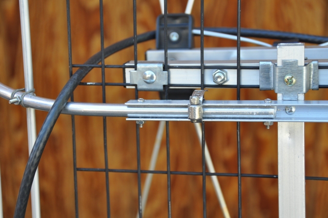
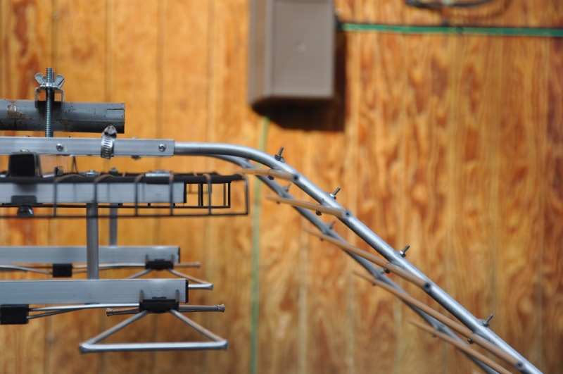
In the following two photos you can observe the mounting arrangement of the reflector support rods. First, two vertical pieces of 1/2" aluminum channel were mounted to the existing horizontal support members. The short ends of the 3/8" support rods are then pressed into the channel. The inside dimension of the channel provides a delightfully snug fit for the 3/8" rod. Initially just a small hose clamp was used to adjust and secure the support rod positions, and then holes were drilled and the rods secured with 6-32 machine screws.
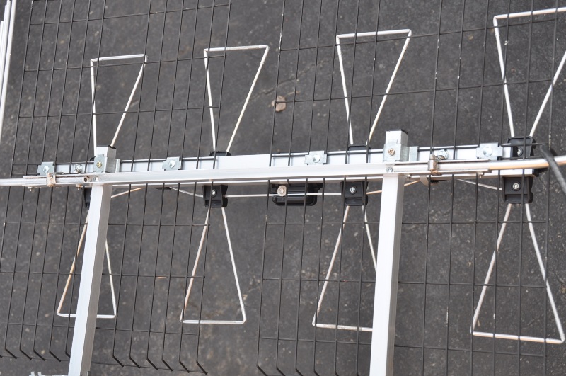
This photo shows the full length of the mounted support channel and rods.
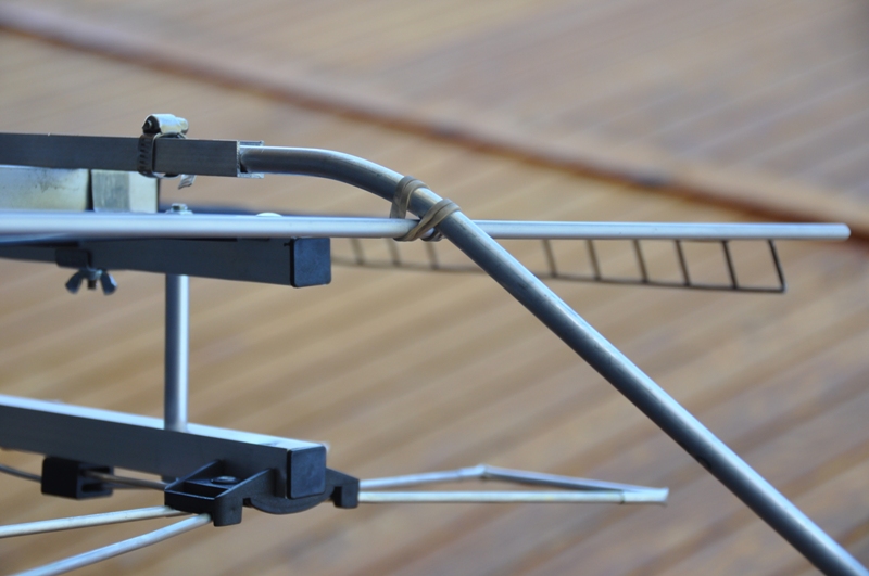
Here, you can see the first (inner most) rod temporarily held in position, and the importance of the 3" radius bend of the support rods becomes evident. It provides the appropriate mounting position for that first rod such that it is exactly on the plane of the existing DB8 reflector. In truth, its probably not that critical, but I didn't want it behind the existing reflector horizontally, nor too far above the existing reflector vertically.
And here is a side view of the completed assembly again illustrating the inner most reflector on the same place as the existing DB8 reflector.
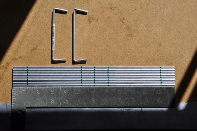
Now, a little different kind of fun. Here you see the stock 3/16" tubing marked for cutting. The choice of a 4" vertical span is probably not optimal. I confess it was simply driven by frugality. The readily available Ace Hardware 3/16" tubing comes in 12" lengths. So I realized I could get two stubs out of each, if I used a 4" length, with 1" on either end to go over the existing whiskers.
So here you see the 12" lengths marked at the center line for cutting in half, and each of those 6" pieces marked at 1" from each end for the bend.
Bending needs to be done gently and slowly. I did it by using my thumb to press the bend mark against the sharp edge of a counter top to get the initial crease, and then slowly continuing the bend until the approximate shape was achieved. Care is also needed to insure that both ends point in the same direction radially.
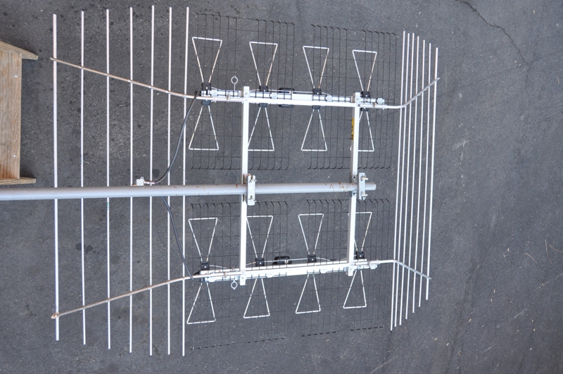
Here you can see the final assembly, illustrating the stubs mounted on all whiskers, the fully assembled and attached reflectors, and the swapped out harness.
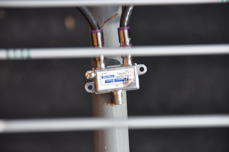
This is a close up of the attached harness. I didn't care for the fact that the stock model weaved the RG6 through the small space to one side of the vertical transmission line, where it was wedged directly against one side of the transmission line conductor, and then to the balun. In that arrangement it could introduce a small imbalance to the transmission line (I theorized). So I took care to bring the RG6 directly down the center line of the vertical transmission line, out to the back of the reflector and then to the middle to connect to the combiner.
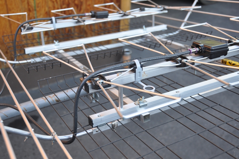
Finally, the PV23-233 combiner.