CM-4228HDNist Harness Construction Info
Some General Mechanical Info
The main thing I ran into was the issue that the distance between
the left and right vertical supports, and thus the distance between centers of the terminals of the left and right
bays, is 20”. In contrast the Nist design called for a 5.2” 'A'
section followed by a 6” 'B' section, “… plus whatever it takes to get to the
terminals”. But even without the terminal part we’re at 5.2 + 6 = 11.2,
and times 2 that’s 22.4”.
Either the A or B section length requirement has to be compromised in order to get a bend at 20” to bring the rails forward to the vertical transmission line terminals.
I compromised the B section. E.g., the bend forward begins at about 5”
along the B section. Further, the B section spacing (optimally .714”) has
to be transitioned to the terminal spacing of 1.5", and rotated 90 degrees as
well.
To make it even more perplexing, I realized quickly that even with the bend
beginning at the 20” spacing, the 2.4” left over, 1.2” on each side, was
insufficient to reach the terminals without touching the vertical support boom.
In other words, to accomplish the rotation forward towards the terminals, and
reach enough separation between rails to clear that vertical boom comfortably,
the transmission line needs to be at least a couple of inches back from the
vertical booms.
So…. I started by cutting two identical 24” pieces of .1"
aluminum wire, marking their centers, and marking the 5.2” transition point.
Then I made the turn forward. The 5” point along the B section occurs
about midway through that 90 degree turn forward. I then tried to maintain
the .714” separation of the rails as long as I could coming out of that turn,
but by about 5.5” the rails have already diverged significantly.
I guess the main concern is the 6” point of the B section is reached somewhere about the middle of a transition from .714” to 1.75”. So the B section is a little short.
Empirically I found it takes about .75” of the material to make a loop for the terminal screw to pass through, and about another .25” to make a quick 90 bend toward the rear. So, from center out the dimensions of this implementation are:
- A 5.2” A section terminating in the middle of a transition from .255” to .714”
- An approximately 5” B section,
- An approximately .8” transition from .714” to 1.75”
- A .25” section that makes a 90 degree bend just before the terminal loop
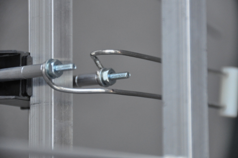
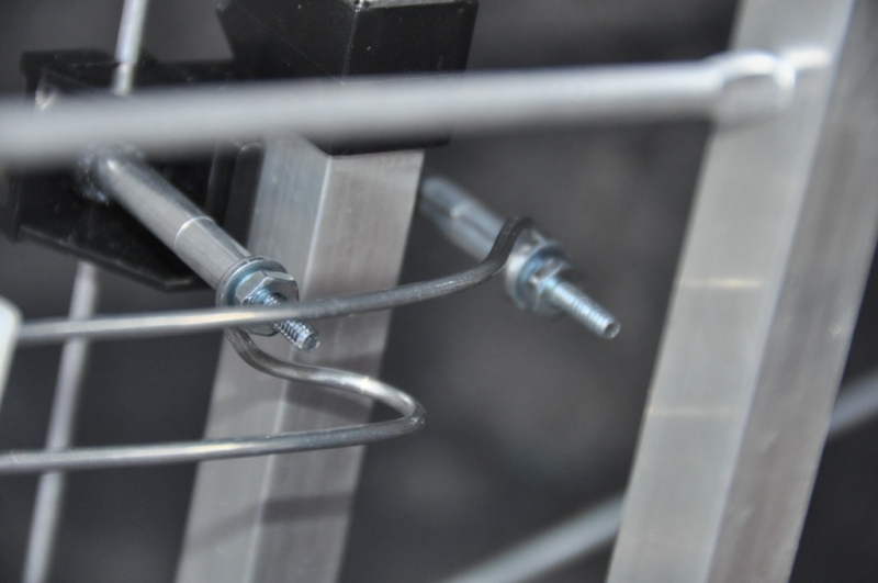
I extended the terminals screws 1.5” toward the rear with aluminum spacers
Transition Detail
The following drawing provides details of the spacing transition.
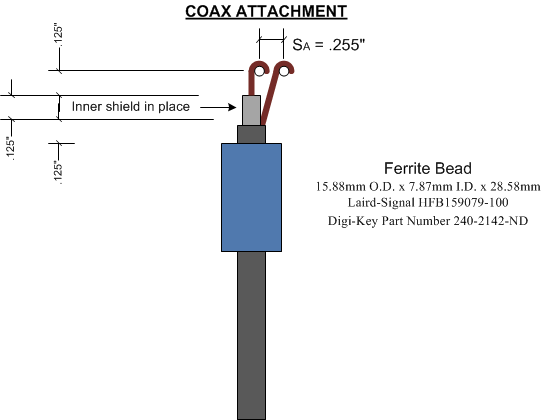
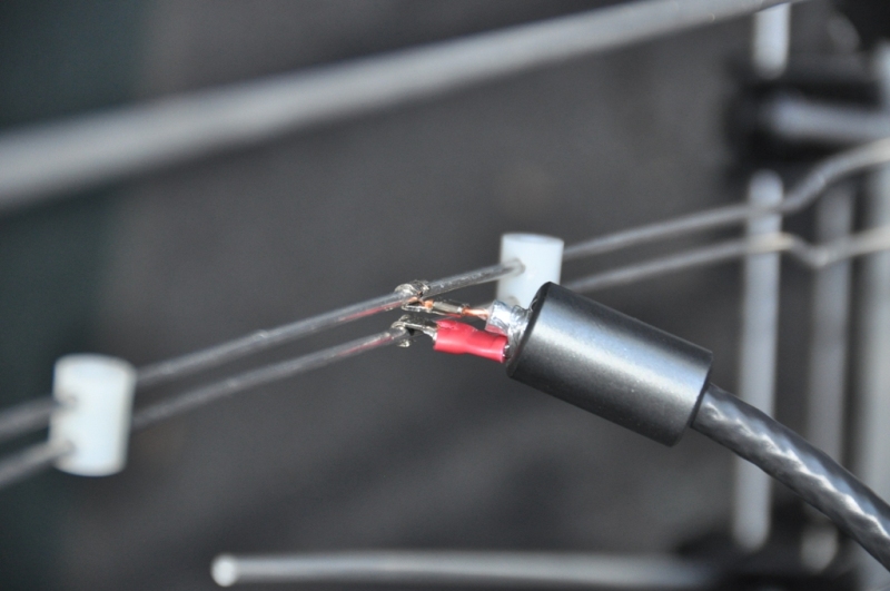
Coax Attachment
I used a couple of spade lug terminals to attach to the .1" wire, wrapping them partially around the wire and cripping. The following illustration provides some details.
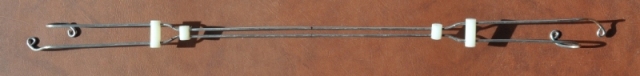
A Few Pictures
The harness prior to attachment.
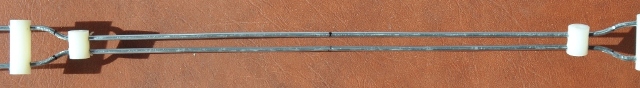
A closeup showing the overall midpoint and transition midpoint markings.
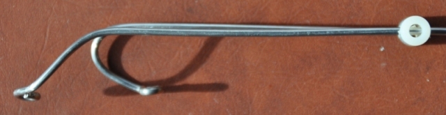
A closeup of the right side, illustrating the transition to the vertical transmission line, as seen from rear.
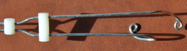
A closeup of the left side, illustrating the transition to vertical transmission line as seen from the bottom.
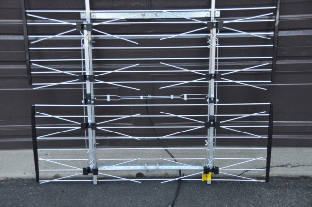
A front view of the final assembly.
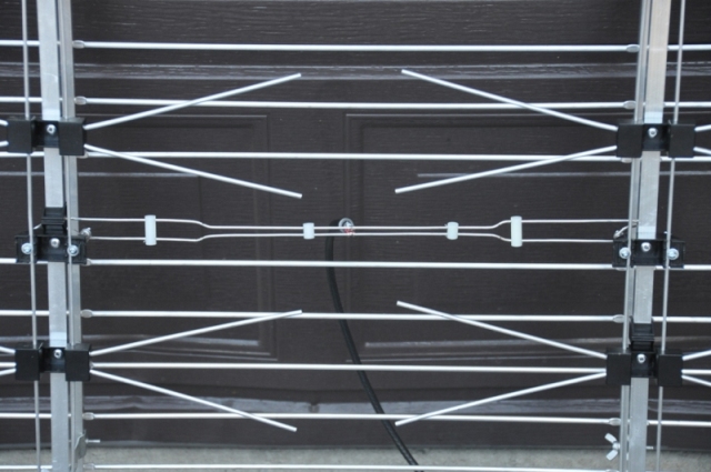
A closer view of the final assembly.
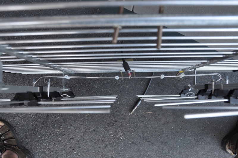
A top view.
The coax attachment.
A closeup of the left side attachment to vertical transmission line.
A closeup of the right side attachment to vertical transmission line.
Parts:
Wire: From whimsie.com, "Medium Stiff Aluminum Wire, 10 gauge", available here.
Ferrite Bead: Laird-Signal HFB159079-100, DigiKey part # 240-2142-ND